


Peripheral interface adaptation
Check both interface standards and the full pin mapping; a passive adapter does not convert protocols.
 ISO 9001 · ISO 13485 · IATF 16949 · ISO 14001 certified manufacturer
Explore products in this family. Open a product for details, or send us your drawing for a custom build.
| Part number | Description |
|---|---|
| QR04AC117 TL359 | M12F STR TO CUT 22AWG 05POL |
| ICX14T1NTL5M | M12 MALE/RJ45 PLUG, CAT 6A, SHIE |
| BCC0E2K | CONNECTION 1=M12X1-MALE, STRAIGH |
| BCC0E2F | CONNECTION 1=M12X1-MALE, STRAIGH |
| DC PLUG-P1J-R1B | BARREL ADAPTER 2.1X5.5X11 TO 5PI |
| ICX14T1NTL1M | M12 MALE/RJ45 PLUG, CAT 6A, SHIE |
| QR04AC118 TL400 | RJ45M/M12F REC 04 POLE |
| ICD14T1NTL20M | M12 MALE D-CODE, STRAIGHT, RJ45, |
| QR04AC117 TL401 | RJ45M/M12F REC 04 POLE |
| ICX44T1NTL2M | CBL M12 FEM RJ45 JACKET TEAL 2M |
| RJD2103-0050 | AMPHE-DANTE ONE CHANNEL INPUT |
| BC-DC003F | CBL ASY USB C M-M DISPLAYPORT 3' |
| CMP7001M0T00(R) | CBL ASSY BARREL M-F 2P 3.28' |
| USBA1M8C10WH(R) | CBL ASY BARREL JK-M 2.1 USB-A 6' |
| SC-2AZK003F | CBL USB2 A TO LIGHTNING BLK 3FT |
| 10-00240 | CABLE USB-A 5.5X2.1 CNTR POS |
| 4945-K-24 | CBL ASSY BNC PLUG-JACK RG174 24" |
| 1203410505 | CORDSET M12 TO RJ45 CAT6A BLUE P |
| 4945-K-48 | CBL ASSY BNC PLUG-JACK RG174 4' |
| 2200-003003 | CABLE TRACKBALL USB 2.5M |
| LPT2USB | USB TO MODEM LPT2USB |
| 76000195 | CABLE STRAIGHT 4' RJ-45/DB-25M |
| USBA11851M8K9P(R) | CBL ASSY BARREL PLG-USB A PLG 6' |
| DELPE-81DB | CBL M12-8 MALE TO LP CUSTOM |
Between-Series Adapter Cables includes cable assemblies with different connector series at their two ends.
When selecting an assembly, check both interface standards, pin mapping, shielding and any required conversion.
A change of connector format does not prove protocol, signal-level or power conversion. Confirm whether the selected assembly is passive or contains conversion electronics.
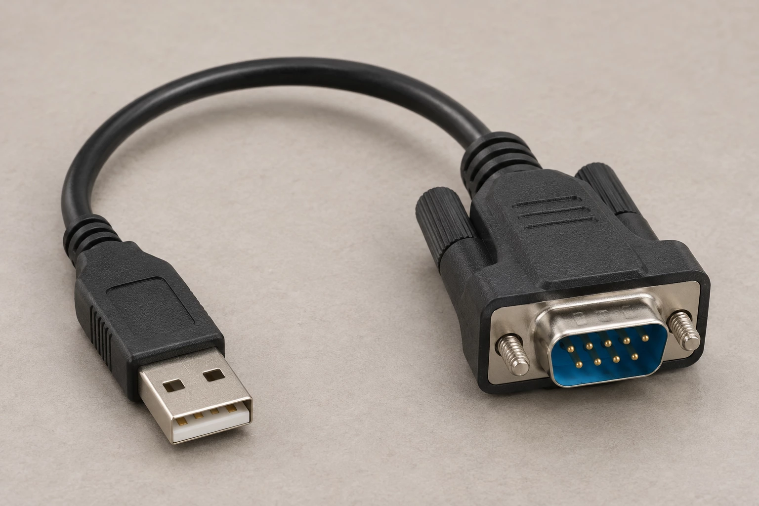
Potential uses vary by part number. Check the listed specifications and equipment requirements before selecting a product.
Check both interface standards and the full pin mapping; a passive adapter does not convert protocols.
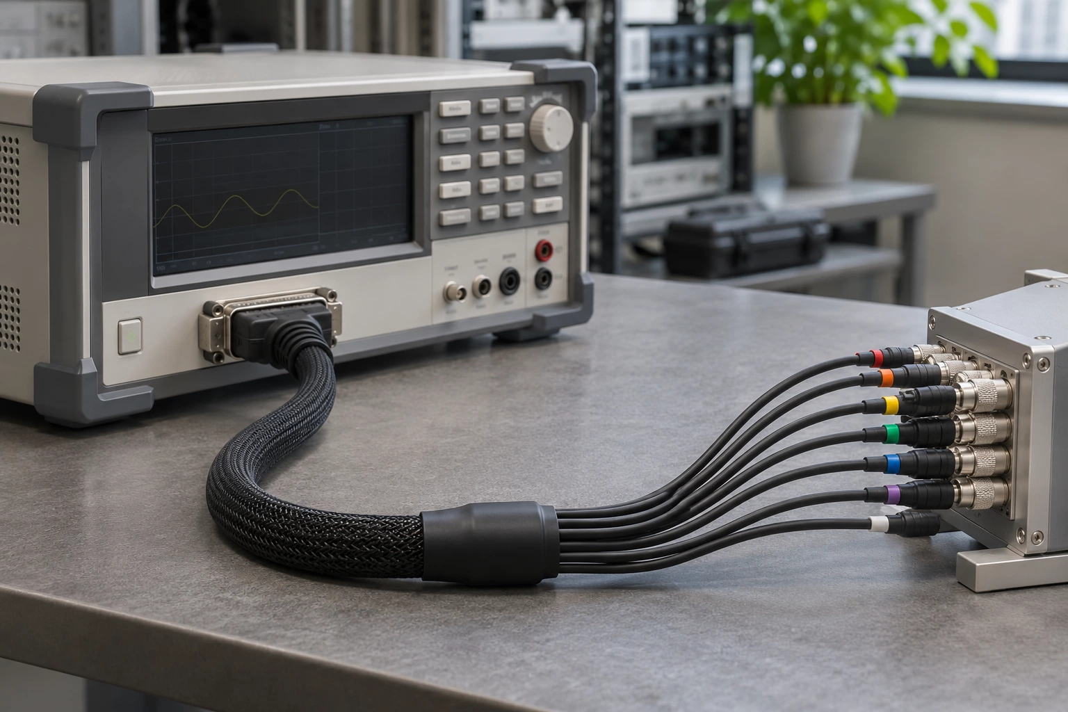
Confirm each breakout connection against the instrument pin assignment and shielding requirements.
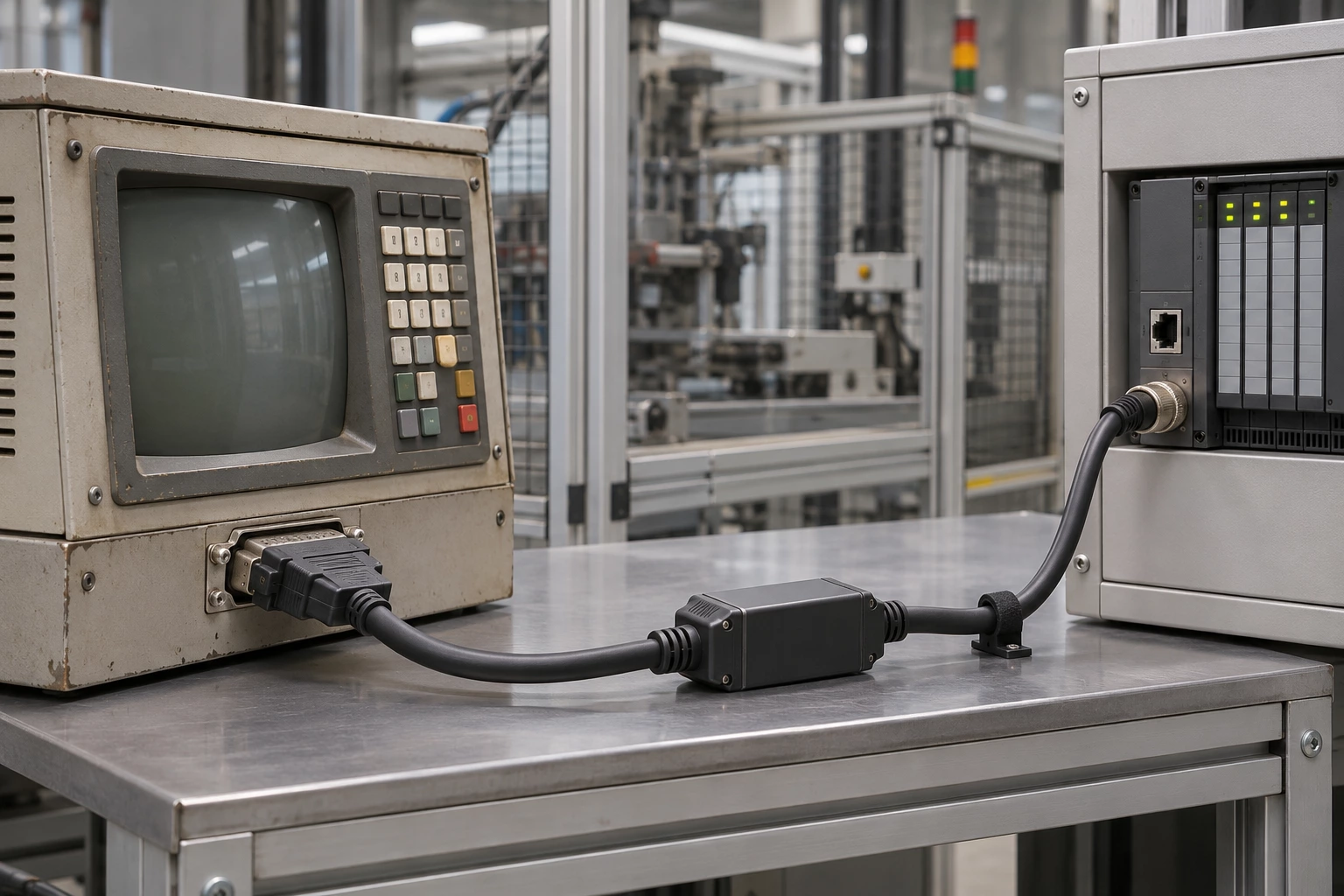
Verify electrical levels and connector functions before integrating the equipment.

Compare the source and destination signals before deciding whether conversion electronics are required.
Compare the interfaces, construction and selection details of these two product options.
Representative listed part: 1300480291.
Representative listed part: 1300480369.
The comparison describes common construction differences; final suitability depends on your electrical, mechanical and lifetime requirements.
Practical answers to help you prepare your drawing and specifications.
Confirm the source and destination interfaces, signal assignment and equipment requirements. A cable listing that connects two connector series is not, by itself, evidence of electronic conversion or protocol compatibility.
Read the complete Connector Type entry, including position and contact counts. Obtain or compare the wiring diagram so each required signal reaches the intended contact at the other end.
Review the listed Shielding and Cable Type together with both connector terminations. If grounding continuity or shield termination is important, include that requirement in the enquiry and request confirmation for the exact part.
A change of connector format does not prove protocol, signal-level or power conversion. Confirm whether the selected assembly is passive or contains conversion electronics.
1300480291 is shown as shielded adapter cables, with Shielding listed as Shielded. 1300480369 is shown as unshielded adapter cables, with Shielding listed as Unshielded. These are two examples, not a statement that every part has either specification.
Provide the original manufacturer and complete part number, or a drawing. For this range, compare both interface standards, pin mapping, shielding and any required conversion. Identify any requirement not covered by the listing rather than selecting only by length or appearance.
Supply a mating-interface drawing and the required both interface standards, pin mapping, shielding and any required conversion. Add quantity, destination and any inspection requirements. Changes must be reviewed for the selected construction before compatibility, pricing or delivery can be confirmed.
Send a drawing, a BOM, a part number or just one sentence. Our engineers review every enquiry and reply within 24 hours.
We use cookies to collect information about how you use this site. We use this information to make the website work as well as possible and improve our services.more details


