

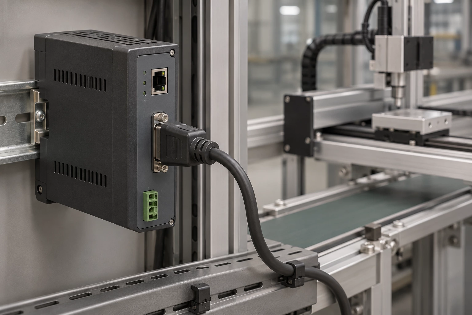
Serial controller links
Confirm the serial standard and pinout; a D-sub shell does not identify the electrical interface.
 ISO 9001 · ISO 13485 · IATF 16949 · ISO 14001 certified manufacturer
Explore products in this family. Open a product for details, or send us your drawing for a custom build.
| Part number | Description |
|---|---|
| MDM-15SH001K | MICRO 15 F 18" YEL JACKS |
| MDM-15PHY01M3-A174 | MICRO 15C P 10CR /11 18" JS NI |
| MDM-15PHY13B | MICRO 21C P /11 10CR 48" |
| MDM-15SH001B | MICRO 15 F 18" YEL |
| MDM-15SH001B-A174 | MICRO 15C SKT 18" YEL NIC |
| MDM-15PHY11P-A174 | MICRO 15C P 10CR /11 36" JP NI |
| MDM-15PHW32B | MICRO 15C P 10CR /33 80" |
| MDM-15PHW22B-A174 | MICRO 15C P 10CR /33 92" NI |
| MDM-15PHC42L-A174 | MICRO 15C P 120" WHT JACKS NI |
| MDM-15PHC42P | MICRO 15C P 120" WHT JACKP |
| MDM-15PHW01P-A174 | MICRO 15C P 10CR/33 18"JACKPNI |
| MDM-15PHC42F-A174 | MICRO 15C P 120" WHT FLOAT NI |
| MDM-15PHC42K-A174 | MICRO 15C P 120" WHT JACKS NI |
| MDM-15PHC42K | MICRO 15C P 120" WHT JACKS |
| MDM-15PHC42B | MICRO 15C P 120" WHT |
| MDM-15PHC42B-A174 | MICRO 15C P 120" WHT NI |
| MDM-31SH008L | MICRO 31C S 12" WHT JACKS |
| MDM-31SH005F-A174 | CABLE ASSY D TO WIRE 31P 762MM |
| MDM-31SH005L-A174 | CABLE ASSY D TO WIRE 31P 762MM |
| MDM-37SH038F | MICRO 37C S 20" YEL FLOAT |
| MDM-31SH004L-A174 | CABLE ASY D TO WIRE 31P 609.6MM |
| MDM-31PH034L-A174 | CABLE ASY D TO WIRE 31P 203.2MM |
| MDM-31PH027F-A174 | MICRO 31C P 3" RBW FLOAT NI |
| MDM-31SH001L-A174 | MICRO 31C S 18" YEL JACKS NI |
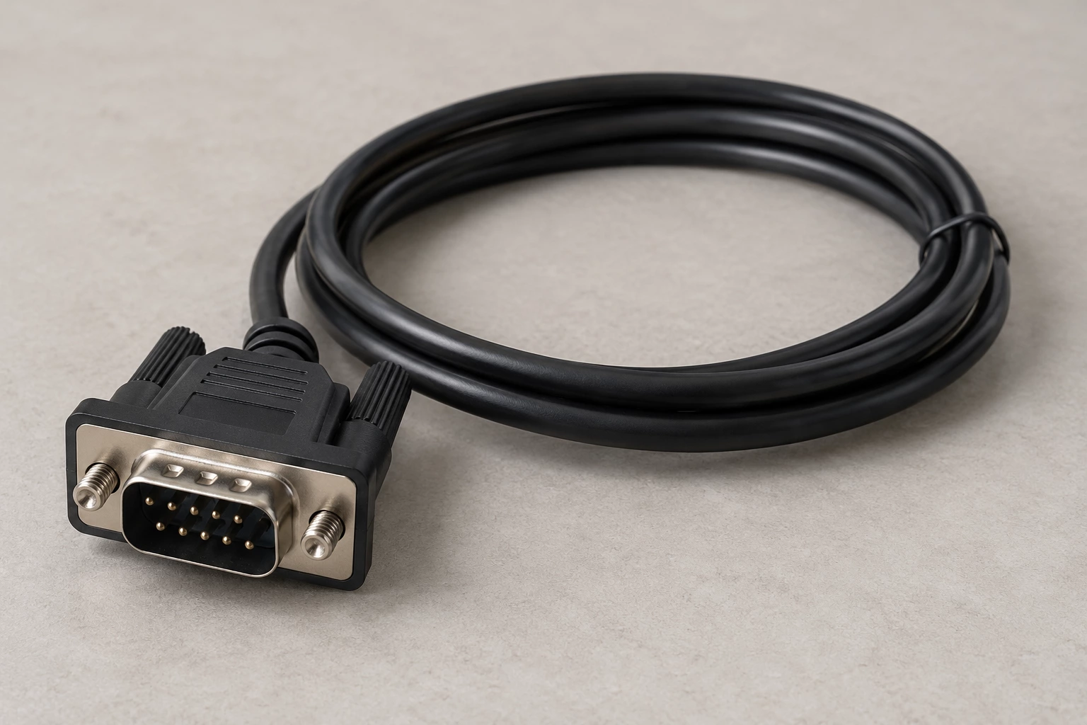
D-Sub Cable Assemblies includes D-sub interconnects with different contact counts and end configurations.
When selecting an assembly, check contact count, gender, pinout, mounting hardware and cable shielding.
Straight-through, crossover and equipment-specific D-sub cables may use similar shells. Confirm the pin-to-pin map instead of inferring it from the connector size.
Potential uses vary by part number. Check the listed specifications and equipment requirements before selecting a product.
Confirm the serial standard and pinout; a D-sub shell does not identify the electrical interface.
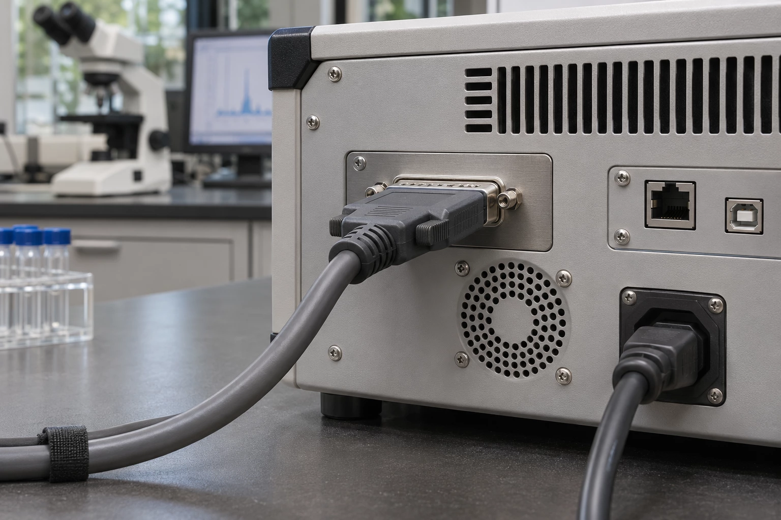
Check contact count, gender and screw-lock hardware against the instrument drawing.

Distinguish straight-through, crossover and equipment-specific wiring before replacement.
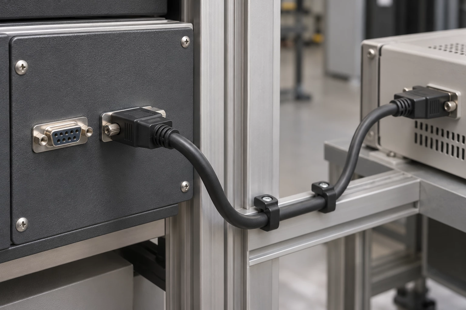
Match both ends and allow clearance for the backshell, mounting screws and cable bend.
Compare the interfaces, construction and selection details of these two product options.
Representative listed part: 1200980207.
Representative listed part: M7OOK-0906J.
The comparison describes common construction differences; final suitability depends on your electrical, mechanical and lifetime requirements.
Practical answers to help you prepare your drawing and specifications.
Check both mating ends and obtain the pin-to-pin wiring required by the equipment. Position count identifies only part of the connection; it does not document straight-through wiring, crossovers or unused contacts.
Read the contact description at both ends and compare it with the equipment connector. Specify the shell size, position count and retention arrangement as well as male pins or female sockets.
Confirm the lead identification, length and termination requirements for the installation. A connector-to-leads assembly requires a defined wiring plan rather than the same mating arrangement as a fully terminated cable.
Straight-through, crossover and equipment-specific D-sub cables may use similar shells. Confirm the pin-to-pin map instead of inferring it from the connector size.
1200980207 is shown as male d-sub termination, with 1st Connector listed as Plug, Male Pins. M7OOK-0906J is shown as female d-sub termination, with 1st Connector listed as Receptacle, Female Sockets. These are two examples, not a statement that every part has either specification.
Provide the original manufacturer and complete part number, or a drawing. For this range, compare contact count, gender, pinout, mounting hardware and cable shielding. Identify any requirement not covered by the listing rather than selecting only by length or appearance.
Supply a mating-interface drawing and the required contact count, gender, pinout, mounting hardware and cable shielding. Add quantity, destination and any inspection requirements. Changes must be reviewed for the selected construction before compatibility, pricing or delivery can be confirmed.
Send a drawing, a BOM, a part number or just one sentence. Our engineers review every enquiry and reply within 24 hours.
We use cookies to collect information about how you use this site. We use this information to make the website work as well as possible and improve our services.more details


