

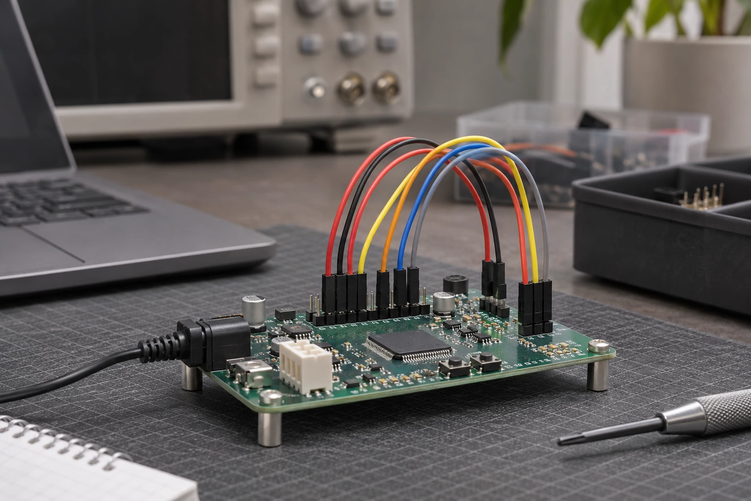
Harness junctions
Wire Splice Connectors can be evaluated for harness junctions. Match wire range, conductor count, splice method and insulation to the equipment interface.
 ISO 9001 · ISO 13485 · IATF 16949 · ISO 14001 certified manufacturer
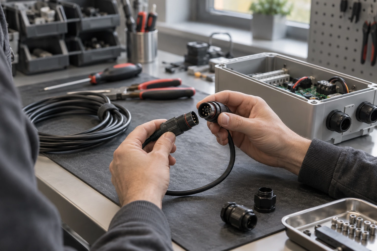
Explore products in this family. Open a product for details, or send us your drawing for a custom build.
| Part number | Description |
|---|---|
| 1601695-1 | CONN SPLICE 13-16.5 AWG CRIMP |
| 41627-1 | CONN SPLICE 4000-10000 CMA CRIMP |
| 51892 | CONN INLINE 8 AWG CRIMP |
| 41996 | CONN SPLICE 7400-10000 CMA CRIMP |
| SGRP-1-1000 | CONN WIRE CAP 1400-4800 CMA TWST |
| 170152-2 | CONN SPLICE 15-22 AWG CRIMP |
| 61300-1 | CONN SPLICE 10000-16000CMA CRIMP |
| 31834 | CONN SPLICE 10-12 AWG CRIMP |
| D-436-86CS788 | CONN SPLICE 16-24 AWG CRIMP |
| 41904 | CONN SPLICE 7000-13000 CMA CRIMP |
| 61769-1 | CONN SPLICE 1200-2600 CMA CRIMP |
| D-436-87CS2705 | CONN SPLICE 12-22 AWG CRIMP |
| 324893 | CONN SPLICE 10-12 AWG CRIMP |
| 55824-1 | CONN SPLICE 18-22 AWG CRIMP |
| D-436-42CS246 | CONN SPLICE 20-24 AWG CRIMP |
| 1601561-1 | CONN SPLICE CRIMP |
| D-440-0109 | CONN SPLICE 1900-6755 CMA CRIMP |
| 134540-1 | CONN SPLICE 14-16 AWG CRIMP |
| 34319-1 | CONN INLINE 6 AWG CRIMP |
| 42627-4 | CONN SPLICE 3200-8200 CMA CRIMP |
| 328860 | CONN SPLICE CRIMP STRATO-THERM |
| 280007-1 | CONN SPLICE 600-3000 CMA CRIMP |
| 553744-4 | CONN INLINE TAP 19-26 AWG CRIMP |
| 5-1377173-1 | CONN SPLICE 22-26 AWG CRIMP |
The Wire Splice Connectors range covers connections joining compatible wire conductors.
Compare wire range, conductor count, splice method and insulation for the required installation. Use the exact mating part and installation dimensions specified for the selected item.
Review Terminal Type, Number of Wire Entries, Termination, Wire Gauge and Insulation on the individual product page before choosing a part.
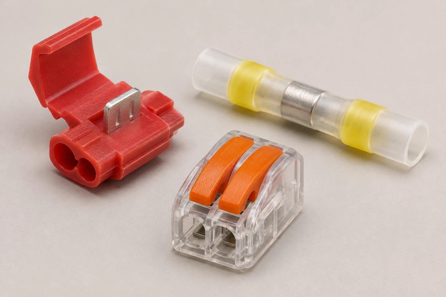
Potential uses vary by part number. Check the listed specifications and equipment requirements before selecting a product.
Wire Splice Connectors can be evaluated for harness junctions. Match wire range, conductor count, splice method and insulation to the equipment interface.
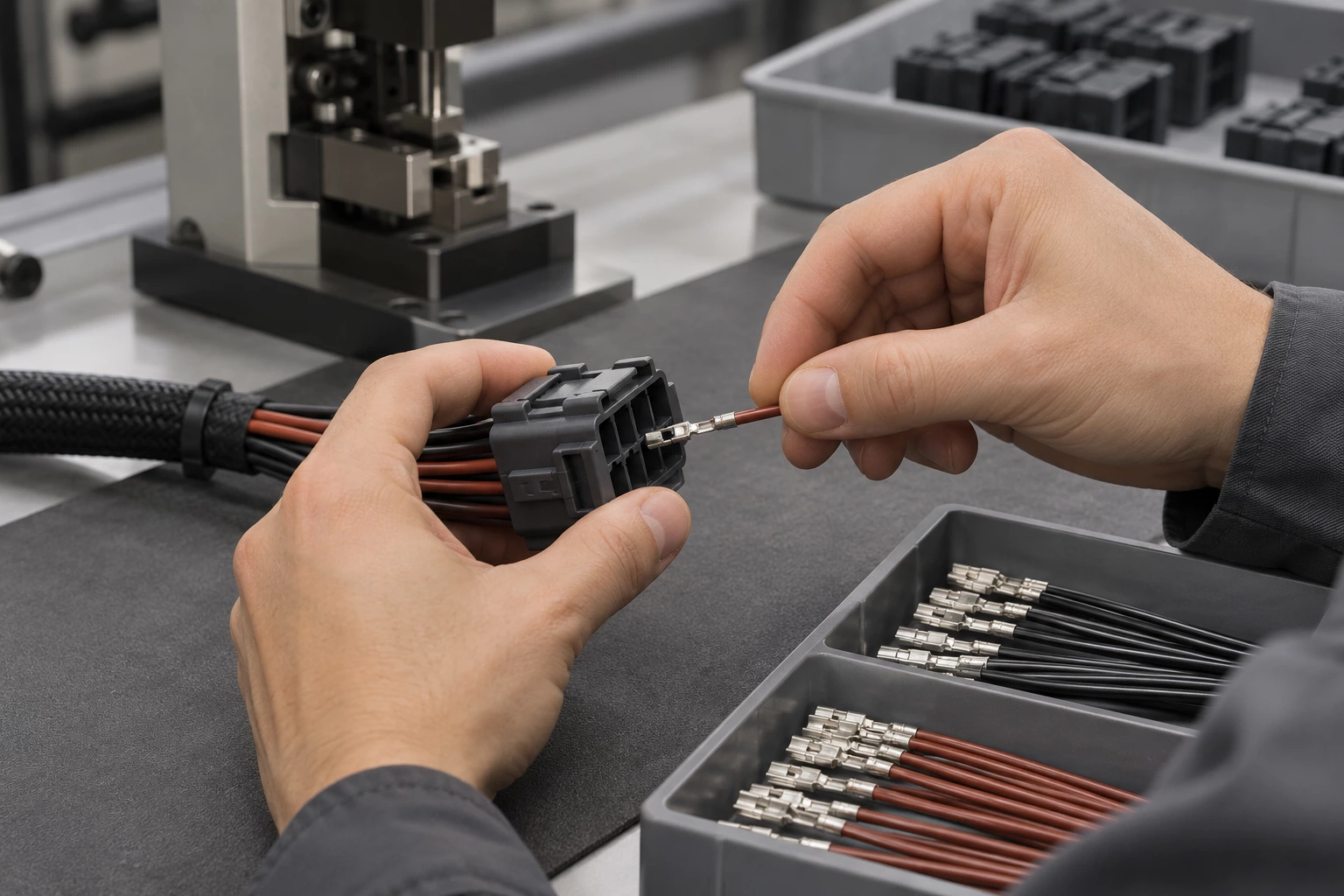
For equipment wiring, verify Terminal Type, Number of Wire Entries, Termination, Wire Gauge and Insulation on the selected Wire Splice Connectors. Use the exact mating part and installation dimensions specified for the selected item.
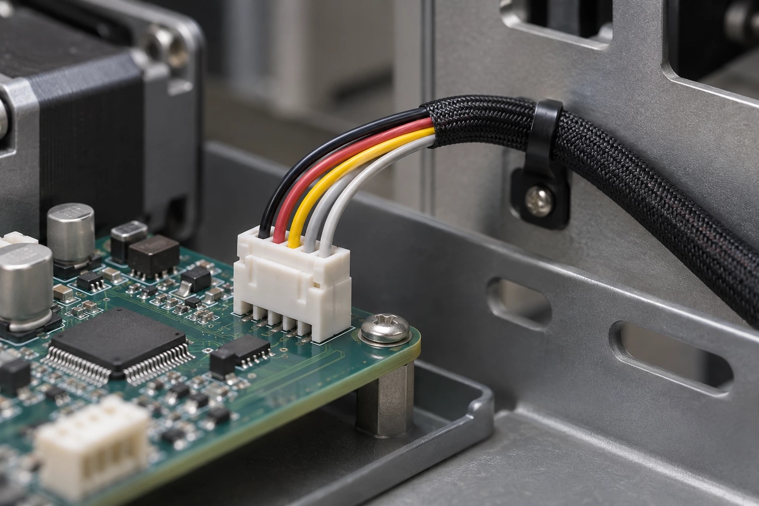
In splice verification, allow for the required mounting, routing or termination space. Check wire range, conductor count, splice method and insulation before assembly.

For wire splice connectors inspection, identify the original Wire Splice Connectors part number and mating arrangement. Compare Terminal Type, Number of Wire Entries, Termination, Wire Gauge and Insulation before substitution.
Compare the interfaces, construction and selection details of these two product options.
Example: 11545
Example: 191540030
The comparison describes common construction differences; final suitability depends on your electrical, mechanical and lifetime requirements.
Practical answers to help you prepare your drawing and specifications.
This category covers connections joining compatible wire conductors. Use the exact mating part and installation dimensions specified for the selected item.
Examples in this category include Butt Splice, Inline, Individual Openings, Inline, Individual Openings (Parallel) and Butt Splice, Closed End, Individual Openings. Match the selected Wire Splice Connectors to the required wire range, conductor count, splice method and insulation.
For Wire Splice Connectors, check Terminal Type, Number of Wire Entries, Termination, Wire Gauge and Insulation against the equipment or mating-part drawing. Confirm the installed clearance and termination access as well as the nominal interface size.
Check wire range, conductor count, splice method and insulation for the selected part. Use its stated operating conditions and complete assembly requirements; appearance alone does not establish the electrical or environmental rating.
Use the exact mating part and installation dimensions specified for the selected item. For Wire Splice Connectors, identify the matching system and required assembly parts before ordering.
11545 specifies Terminal Type: Butt Splice, Inline, Individual Openings and Number of Wire Entries: 2. 191540030 specifies Terminal Type: Butt Splice, Inline, Individual Openings and Number of Wire Entries: 2. Check the full mating and installation requirements before treating different Wire Splice Connectors as replacements.
Send the manufacturer and full part number, quantity and required delivery destination. For this category, include wire range, conductor count, splice method and insulation and a mating or installation drawing when a replacement is needed.
Send a drawing, a BOM, a part number or just one sentence. Our engineers review every enquiry and reply within 24 hours.
We use cookies to collect information about how you use this site. We use this information to make the website work as well as possible and improve our services.more details


